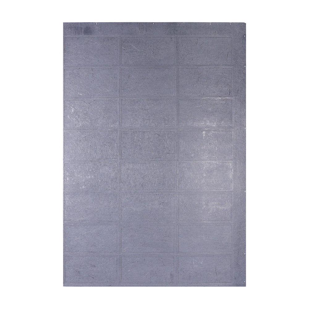
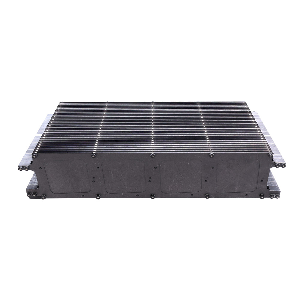
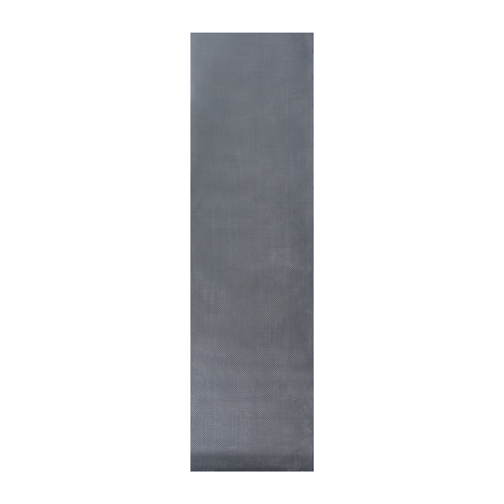
The Battery Field category covers the carbon-carbon carriers that hold solar cells in place during their most delicate processing steps — HJT substrate carriers, Top-Con carbon-carbon boats, and Perovskite long fiber boards — each built to move cells through high-temperature coating, diffusion, and sintering steps without warping, sagging, or reacting with the active cell surface.
HJT substrate carriers hold wafers flat and evenly spaced during plasma-enhanced chemical vapor deposition, where low thermal mass and even heat distribution directly affect the amorphous silicon layer quality and, in turn, cell efficiency.
Top-Con carbon-carbon boats carry wafers through high-temperature diffusion and tunnel-oxide passivation steps, holding tight cell-to-cell spacing across a full boat load without dimensional drift.
Perovskite long fiber boards give a flat, low-mass carrying surface for perovskite and tandem cell process steps that call for gentle, uniform heating with minimal surface reactivity.
The same low-contamination, dimensionally stable carriers support pilot lines and R&D programs developing new heterojunction, Top-Con, and tandem cell architectures.
The carriers and boards in this category draw on the same decade of fiber architecture, densification, and purity-control expertise developed across the company's full furnace and thermal-field product range — applied here to the tighter dimensional and cleanliness tolerances that solar cell processing demands.
Purity-control and thermal-stability lessons learned engineering silicon growth and semiconductor thermal fields carry directly into how HJT, Top-Con, and Perovskite carriers are designed and toleranced.
Ten years of matching short-fiber and long-fiber layups to specific thermal-mass and flatness targets means each carrier is built for how it will actually be handled and loaded on a production line.
Long-running work supplying silicon and compound-semiconductor customers has shaped strict low-particulate, low-ash manufacturing controls that carry over into every cell carrier produced for this category.
Preform design, densification, graphitization, and machining are handled in-house end to end, so a process improvement made for one carrier type can be rolled out consistently across HJT, Top-Con, and Perovskite products alike.
Every carrier moves through the same six-stage process, with in-line testing at each stage so an HJT substrate carrier, Top-Con boat, or Perovskite board leaving the factory has already been checked against the flatness, purity, and dimensional spec it was designed to.
Carbon fiber is woven or needle-punched into the target carrier or boat geometry.
Chemical vapor infiltration and pitch/resin impregnation fill the preform with carbon matrix over multiple cycles.
Heat treatment at 2200–2800°C converts the matrix to ordered graphitic carbon, improving conductivity and dimensional stability.
Anti-oxidation or protective coatings are applied where a carrier will be exposed to air at elevated temperature.
Diamond tooling cuts cell pockets, slots, and contours to final tolerance without delaminating fiber bundles.
Flatness, density, ash content, and dimensional checks confirm every batch against spec before shipment.
Production runs under ISO 9001 quality management, supported by a Municipal-Level Enterprise Technology Center and Provincial R&D Center. Customer drawings, wafer specifications, or process parameters are matched to a carrier design and material grade before production tooling begins.
Why use carbon-carbon carriers instead of quartz or metal boats for HJT and Top-Con lines?
C/C carriers combine lower thermal mass than quartz with better thermal-shock resistance than metal, so they heat and cool faster with the process cycle while holding flatness and cell spacing across repeated high-temperature loads. This generally supports higher throughput and fewer carrier replacements than either alternative.
How do cell carriers affect HJT and Perovskite cell efficiency?
Uneven heating or carrier sag during PECVD coating or annealing steps can create thickness or temperature variation across the cell surface, which shows up later as efficiency loss. A flat, low-mass, purity-controlled carrier reduces this variation and helps keep coating uniformity consistent from cell to cell.
Can carrier layout be customized for a specific wafer size or cell count?
Yes. Cell-pocket pitch, board dimensions, and boat slot count are adjusted to match the customer's wafer size and line configuration, so a carrier can be built to drop into an existing HJT, Top-Con, or Perovskite process tool without redesigning the tool itself.
What causes contamination risk in solar cell processing, and how do C/C carriers help?
Metallic particulates from fixtures or fittings can transfer onto a wafer surface during high-temperature steps and reduce cell performance. Because C/C carriers are pure carbon with controlled ash content, they remove one of the common contamination pathways that affect sensitive HJT and perovskite surfaces.
What temperature range are HJT, Top-Con, and Perovskite carriers rated for?
Rated temperature depends on the specific carrier and coating, but C/C carriers in this category are generally built to handle the full diffusion, oxidation, and PECVD coating temperature range used in current HJT and Top-Con production lines without losing flatness or structural integrity.
How does the ordering and customization process work?
Customers typically share wafer size, cell count per carrier, and target process parameters (temperature, atmosphere, cycle time). These are matched to a carrier design, fiber architecture, and purity grade before production tooling is set up, so the finished carrier fits the intended process step from the start.