Carbon Carbon Composites: Complete Industry Knowledge Guide

Carbon carbon (C/C) composites combine a carbon fiber reinforcement with a pure carbon matrix, producing a structural material that keeps its strength, shape, and purity at temperatures where metals soften, ceramics crack, and standard graphite wears out too fast. Because fiber and matrix are chemically identical, C/C parts run continuously above 2000°C in vacuum or inert atmosphere, resist thermal shock across thousands of heating cycles, and hold tolerances tight enough for silicon crystal growth, compound semiconductor synthesis, and vacuum sintering. Zhejiang Dehong Carbon Fiber Composite Material Co., Ltd. manufactures the full component set for these environments — from crucible holders and furnace heaters to insulation felt and structural preforms — engineered and produced in-house rather than assembled from third-party parts.


Technical Specifications

Property Typical Range Why It Matters
Bulk density 1.60 – 1.95 g/cm³ Roughly a quarter the density of steel; lowers rotational and thermal mass
Max continuous service temperature (inert/vacuum) up to 3000°C (structural) / 2800°C (felt) Sets the working ceiling for furnace hot-zone design
Thermal conductivity (in-plane) 80 – 350 W/m·K Controls heat distribution across heaters and crucible supports
Coefficient of thermal expansion (fiber direction) 0 – 3 × 10⁻⁶ /K Near-zero movement across thermal cycles; keeps hot-zone geometry fixed
Flexural strength 80 – 300 MPa Determines load capacity of plates, heaters, and support rings
Compressive strength 150 – 400 MPa Governs crucible and melt-load bearing capacity
Ash content / metallic impurities < 5 – 50 ppm depending on grade Protects silicon and compound-semiconductor melt purity
Open porosity < 5% Indicates densification completeness and oxidation resistance
Dimensional tolerance (machined features) ±0.05 – 0.1 mm Required for threaded fasteners, bores, and mating seats

These figures represent baseline material grades; specific components are tuned by fiber architecture and densification cycle to hit the mechanical or purity target for a given furnace position.


Applications

Monocrystal Growth Thermal Field — Czochralski Silicon Pulling

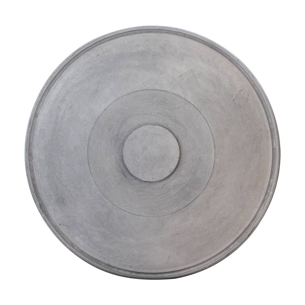
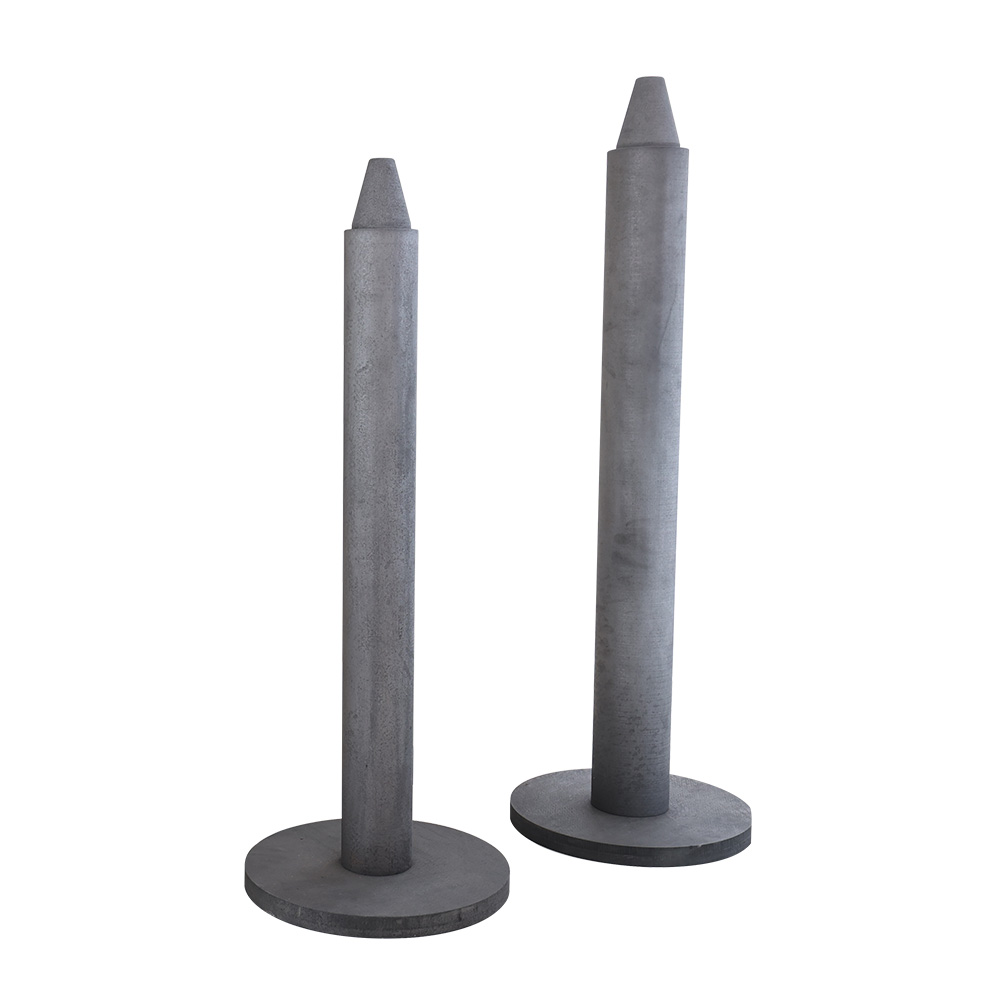
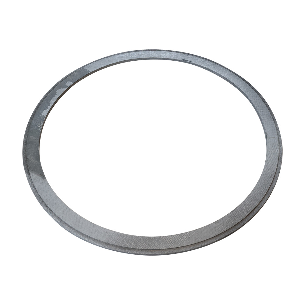
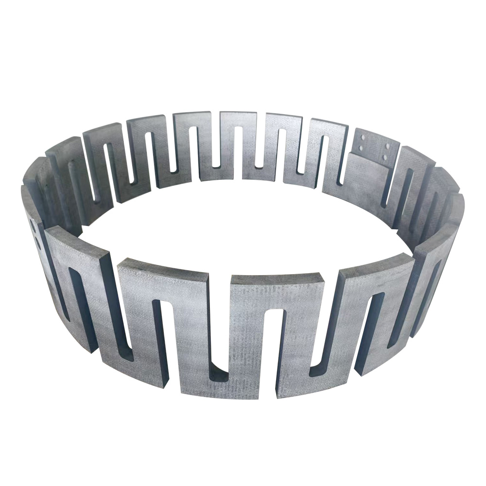
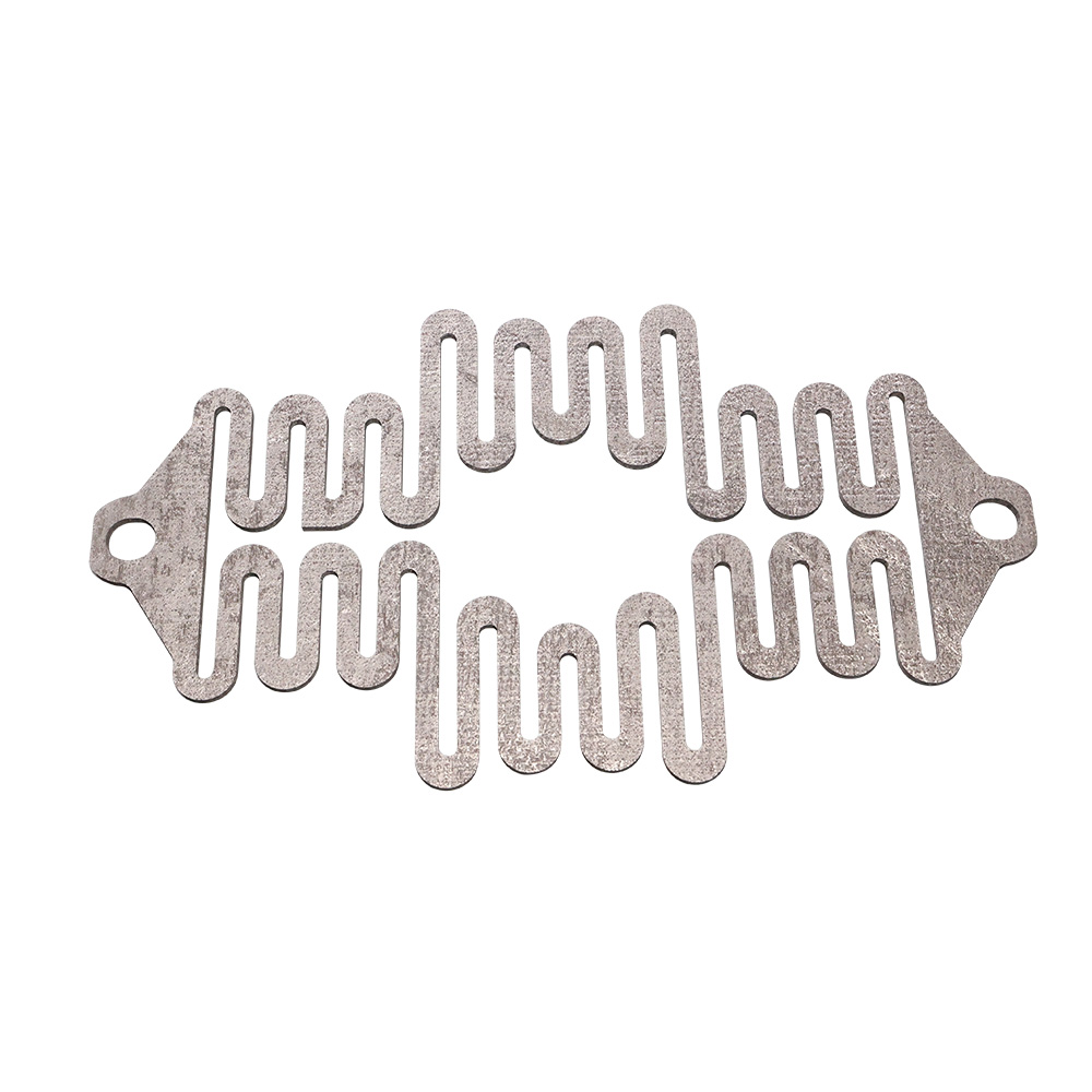
Inside a Monocrystal Growth Thermal Field, the crucible holding molten silicon sits above 1500°C for the entire pulling cycle. A carbon-carbon crucible holder carries this load without creeping out of shape, while a support rod transmits rotation and axial load from the drive shaft. The main heater shapes the radial temperature field that governs the V/G ratio — the single most important variable for defect-free crystal — and a bottom heater trims melt uniformity from underneath. Structural rings and integral insulation felt lock the hot-zone geometry in place across repeated growth runs.

Polycrystal Thermal Field — Directional Solidification

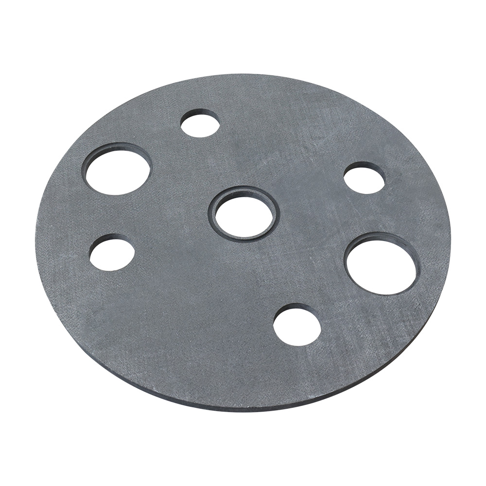
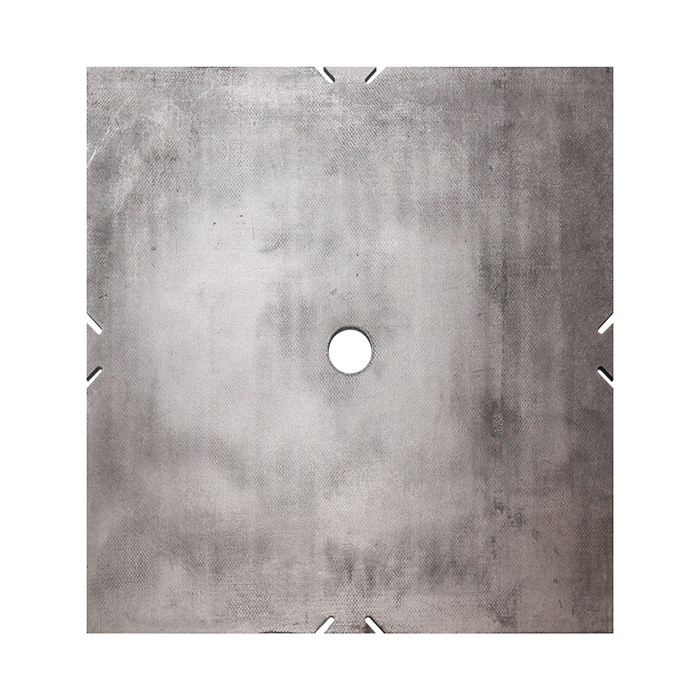
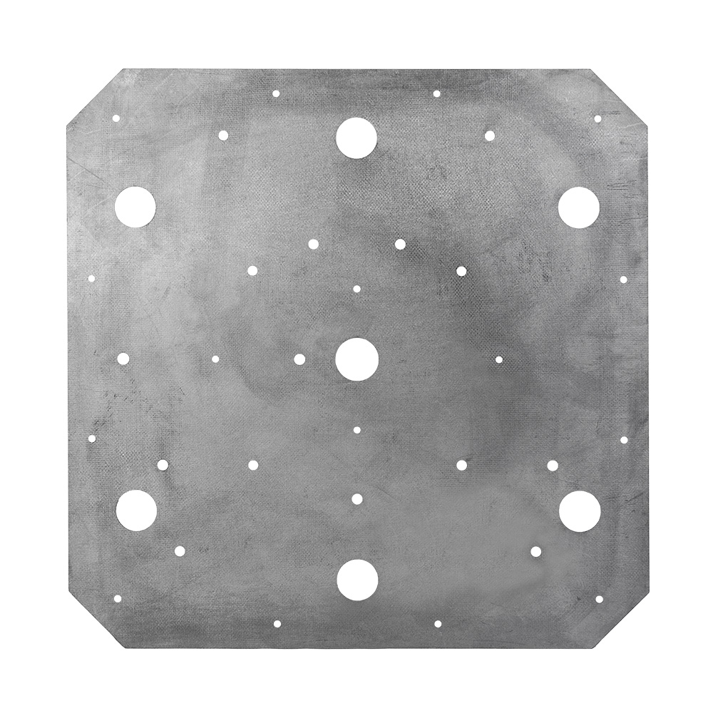
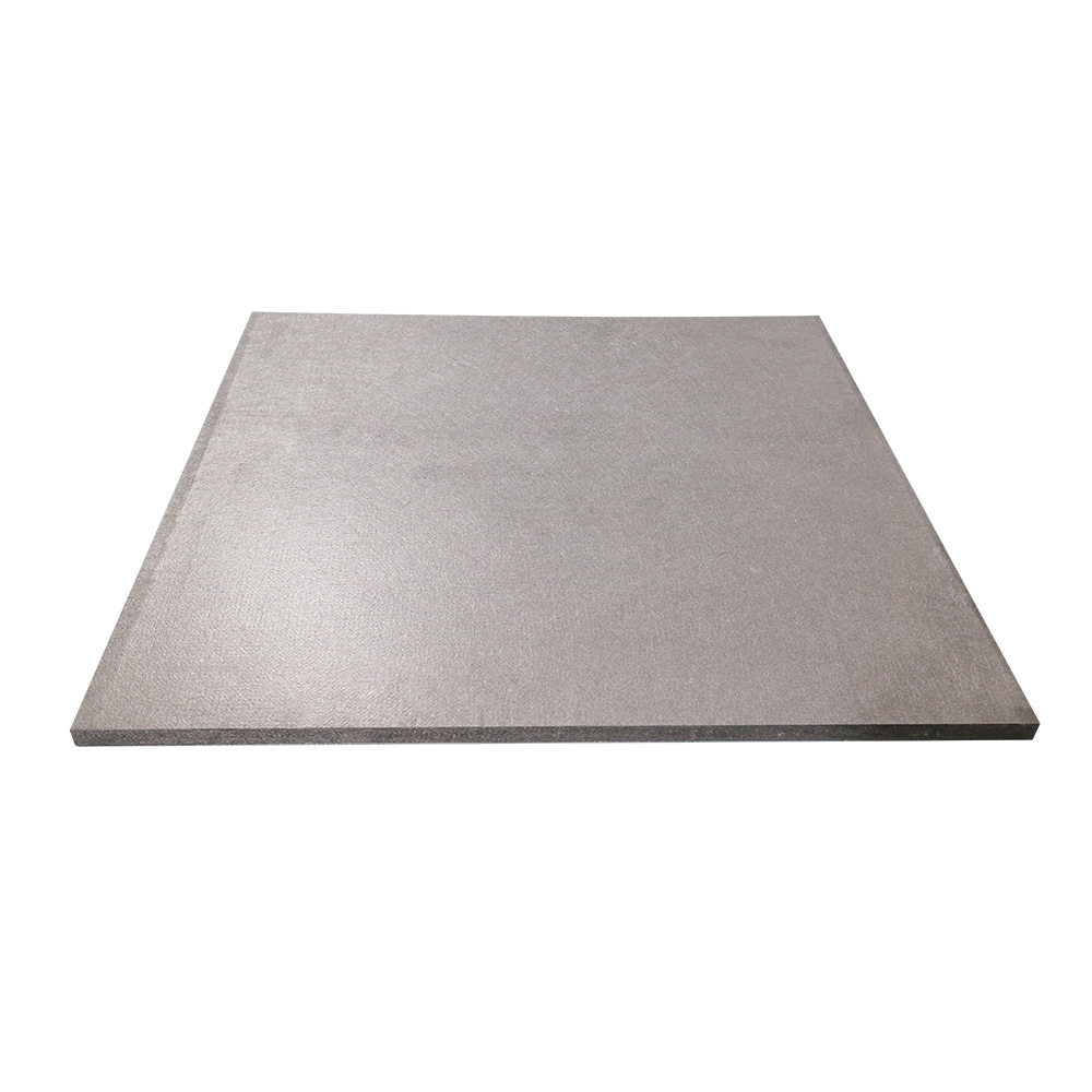
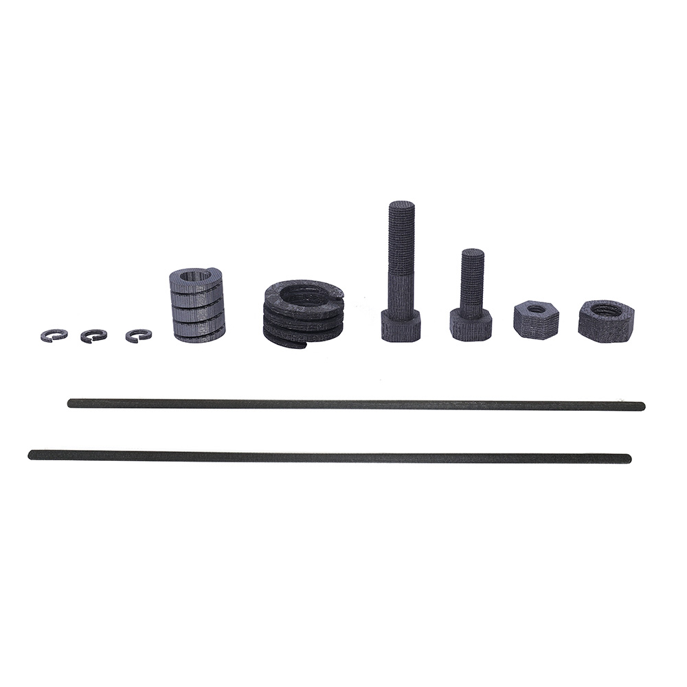
The Polycrystal Thermal Field used for directional solidification of multicrystalline silicon runs 50–70 hour static batch cycles with a controlled top-to-bottom temperature gradient. A cover plate and top plate regulate radiation loss from the melt surface, shaping the solidification front; a protection plate manages lateral heat leakage to keep the front flat and reduce grain boundaries in the finished ingot. C/C fasteners hold the assembly together without introducing metallic contamination at temperature, and a furnace base anchors the whole hot-zone stack.

Solar Cell Terminal — Electrode and Cell-Level Processing

On the cell side, Solar Cell Terminal components support electrode sintering, diffusion, and coating steps where trays, boats, and carriers must not react with active cell materials. An HJT substrate carrier is a specific example — designed for heterojunction cell PECVD coating, where low thermal mass and even temperature distribution directly affect cell efficiency.

Semiconductor Field — Compound Crystal Synthesis and Growth

Compound semiconductor manufacturing (SiC, GaAs, GaN) runs the Synthesis Furnace stage first, where graphite crucibles hold source material through the reaction that fixes stoichiometry. The material then advances to the Crystal Growth Furnace, insulated by soft felt and hard felt tubes that maintain the axial gradient controlling crystal polytype, and supported by graphite epitaxial wafers as susceptors in downstream CVD/MOCVD steps. Because these processes tolerate almost no metallic contamination, purity control at the felt and crucible stage is covered in more depth in an overview of why graphite components are the foundation of every crystal growth furnace.

Vacuum Furnace Field — Sintering, Brazing, Heat Treatment

Inside a Vacuum Furnace Field hot zone running at 10⁻³–10⁻⁶ mbar, hot press molds shape parts under pressure and heat simultaneously, material racks and boat supports carry the workload through the cycle, and card slots secure thermocouples and sensors without shifting under vibration. Overall insulation felt wraps the chamber to cut energy loss; felt-grade selection for this environment is discussed further in soft felt vs. rigid felt: which thermal insulation should you choose.

Carbon Preforms — The Structural Starting Point

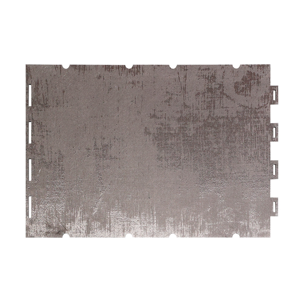
Every C/C part begins as a Carbon Preforms fiber structure before densification. Deposition furnace liners stabilize CVD/PVD chamber environments, tray preforms carry substrates through high-temperature handling steps, and brake disc preforms feed into friction-material densification lines for aerospace and automotive braking systems.


Why Choose C/C Over Graphite, Molybdenum, or Tungsten

Criterion Carbon-Carbon Composite Isostatic Graphite Molybdenum / Tungsten
Thermal shock resistance Excellent — fiber architecture arrests crack growth Moderate — brittle, prone to cracking under fast cycling Good, but prone to recrystallization embrittlement
Density 1.6 – 1.95 g/cm³ 1.7 – 1.9 g/cm³ 10.2 g/cm³ (Mo) / 19.3 g/cm³ (W)
Service life under repeated cycling Long — mechanical integrity retained after thousands of cycles Shorter — surface erosion and cracking accumulate Moderate — grain growth reduces ductility over time
Cost at scale Lower than refractory metals Lowest of the group High raw-material and machining cost
Machinability Diamond tooling, complex geometries achievable Easy to machine Difficult; requires specialized tooling
Contamination risk Very low — pure carbon, no metallic species Low, but softer and sheds particulates faster Risk of metallic vapor transfer at high temperature

Graphite remains a reasonable choice for lower-cycle, cost-sensitive applications. Refractory metals suit environments where extreme mass and rigidity outweigh weight concerns. For high-cycle, high-temperature positions — furnace heaters, crucible holders, structural rings — C/C composites generally deliver the longest service interval per unit cost, which is why Dehong's product range across the solar PV, semiconductor, and vacuum furnace fields is built almost entirely on C/C rather than metal.


Customization Options

  • Fiber architecture: 2D laminate, 2.5D, needled, or 3D woven, selected by load direction (tensile, compressive, flexural, shear)
  • Density grade: 1.60 – 1.95 g/cm³, matched to mechanical or purity requirement
  • Dimensions: support rods from 10–100 mm diameter and 100–500 mm length; felt thickness 5–50 mm; plate thickness 5–30 mm; custom sizing available beyond standard ranges
  • Power rating (heaters): main heaters 1–50 kW; bottom heaters 5–100 kW
  • Purity grade: standard industrial (< 50 ppm ash) up to semiconductor-grade (< 5 ppm total metals)
  • Coating: uncoated for vacuum/inert use, or SiC / TiC / multilayer anti-oxidation coating for air-exposed applications
  • Thread standards and fastener geometry: matched to existing furnace hardware
  • Tolerance class: standard machining down to ±0.1 mm, precision mating surfaces to ±0.05 mm

Customers supply furnace drawings, OEM part numbers, or performance targets (temperature, load, atmosphere), and Dehong's engineering team returns a matched material grade and dimensional spec before production tooling begins.


Manufacturing Process & Quality Control

  1. Preform fabrication — carbon fiber is woven, needle-punched, or filament-wound into the target geometry.
  2. Densification — chemical vapor infiltration (CVI), liquid-phase impregnation (LPI) with pitch or resin, or a hybrid of both fills the fiber preform with a carbon matrix over multiple cycles.
  3. Graphitization — heat treatment at 2200–2800°C converts the matrix to ordered graphitic carbon, raising thermal conductivity and relieving residual stress.
  4. Coating (optional) — SiC, TiC, or multilayer anti-oxidation coatings are applied for parts exposed to air above roughly 400°C.
  5. Machining — diamond tooling cuts threads, bores, slots, and contours to final tolerance without inducing delamination at fiber-bundle boundaries.
  6. Inspection — bulk density (Archimedes method), open porosity, four-point flexural strength, laser-flash thermal conductivity, ICP-MS ash-content analysis, and CMM dimensional verification confirm each batch against spec before shipment.

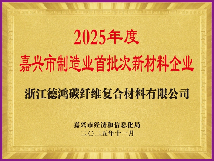
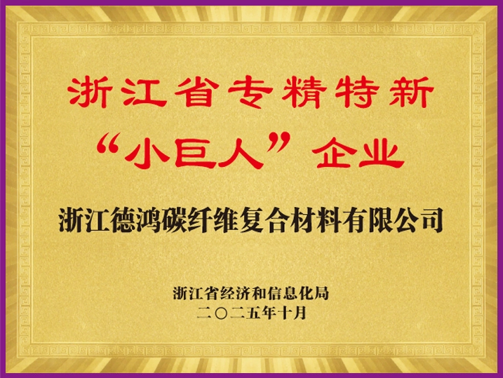
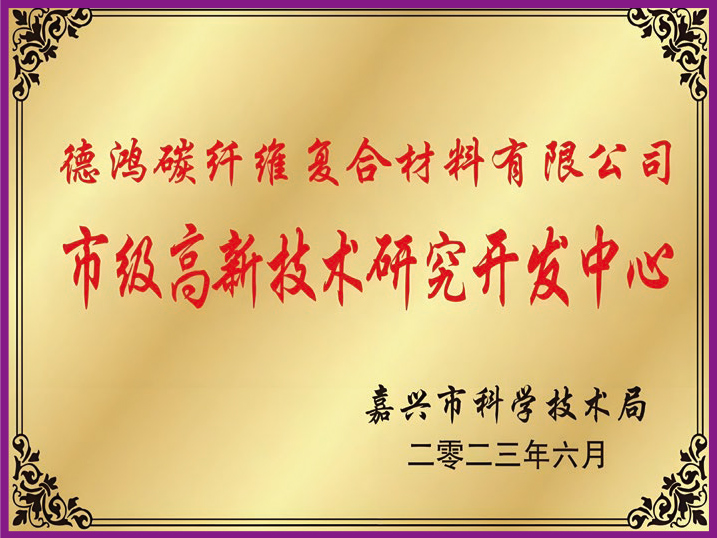
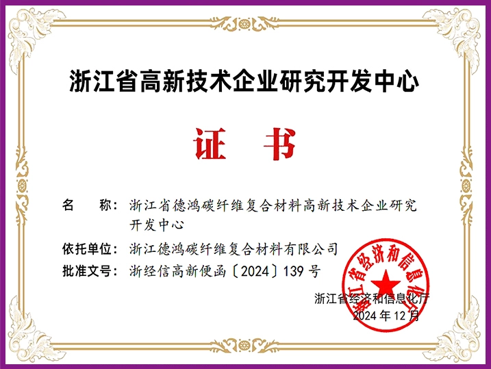
Dehong operates under ISO 9001 quality management, holds a Municipal-Level Enterprise Technology Center and Provincial R&D Center, and has filed over 30 patents covering C/C process and component design.


Related Products

Solar PV Thermal Field: Solar PV Thermal Field · Monocrystal Growth Thermal Field · Polycrystal Thermal Field · Solar Cell Terminal

Semiconductor Field: Semiconductor Field · Synthesis Furnace · Crystal Growth Furnace

Other Fields: Vacuum Furnace Field · Carbon Preforms